The purpose of Lab 6 was to get experience controlling car orientation using the IMU. In this lab we will control
the yaw of our robot using the IMU. For this lab I will be implementing a PI controller.
Lab Set-up/Prelab
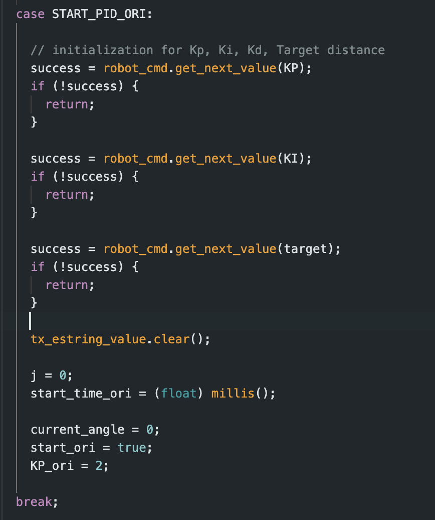
For the prelab of this class I set up code that allows bluetooth communication with the robot, similar to lab 5. I
set up two main cases, START_PID_ORI and STOP_PID_ORI. The START_PID_ORI controls the orientation PID controller
and sends this
data back to the python script. START_PID_ORI sets the KI and KP values as well as the target angle value.
STOP_PID_ORI just stops the car. I decided to use PI control for this lab.
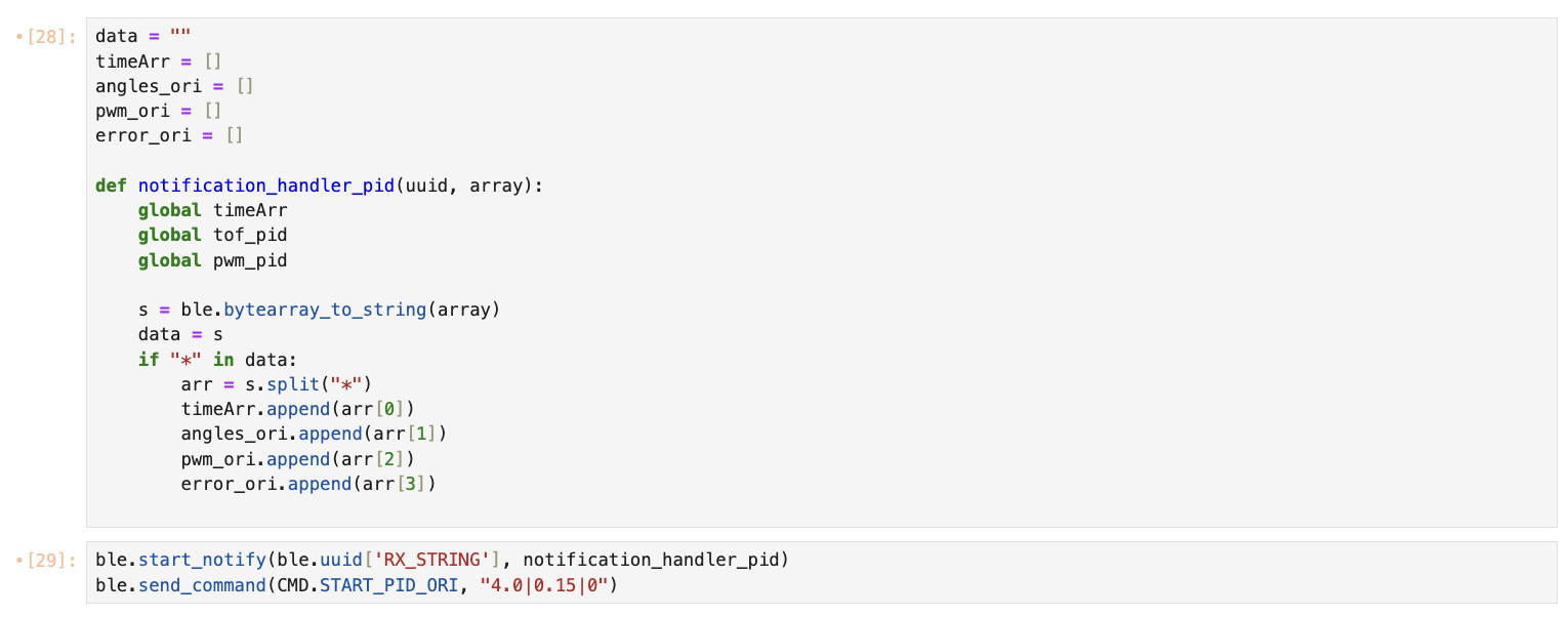
Finally, I created a third case SEND_ORI_DATA that looped through the arrays of Orientation PID data and sent it
back to the Python script.
PID Control Equation
For this lab, we will be using the PID control equation to control the orientation of our robot. I chose to focus
on
PI control since I wanted to get a good understanding of how P and I effects the movement of the car.
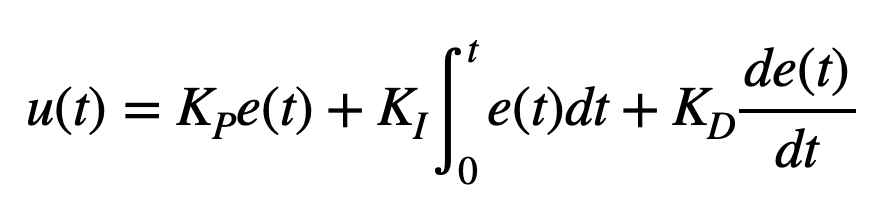
We use the equation from lecture shown below:
The PID equation uses 3 main constants: Kp (proportional constant), KD (derivative constant), and Ki (integral
constant). It uses these constants and the error to calculate the new PID input value. The Proportional control
adjusts output based on error magnitude, with larger errors causing
stronger responses. Integral control accumulates error over time, maintaining correction even when the error
momentarily disappears, ensuring steady-state accuracy. Derivative control responds to error rate changes,
essentially predicting future behavior—like slowing a robot approaching a wall too quickly.
DMP: Digital Motion Processor
The gyroscope data has a lot of drift as seen in Lab 2. Digital integration can also lead to several problems.
This is because of tiny measurement errors and biases
that accumulate over time. Further, discrete sampling can miss high-frequency changes between samples. We can
reduce this drift by using the onboard DMP. This automatically implements sensor fusion. It combines gyroscope,
accelerometer, and magnetometer data internally which significantly reduces drift. To implement DMP I followed the
instructions provided from the lab handout page. I first changed the ICM_20948_C.h header. I then implemented the
code as described.
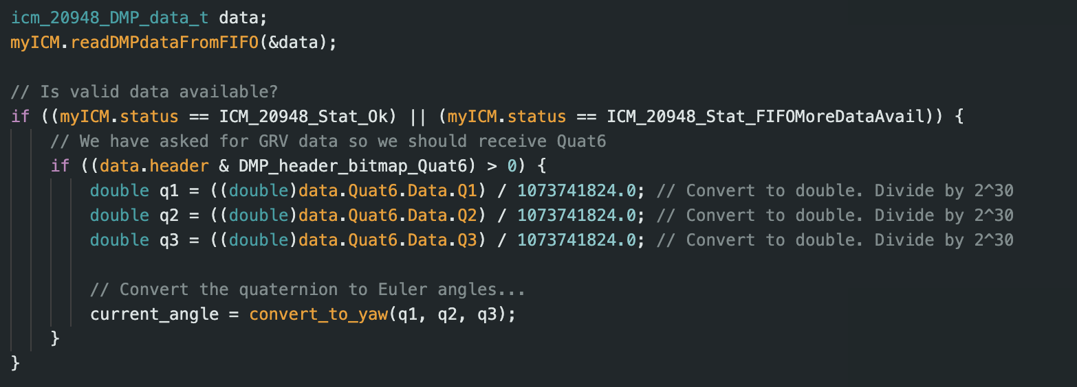
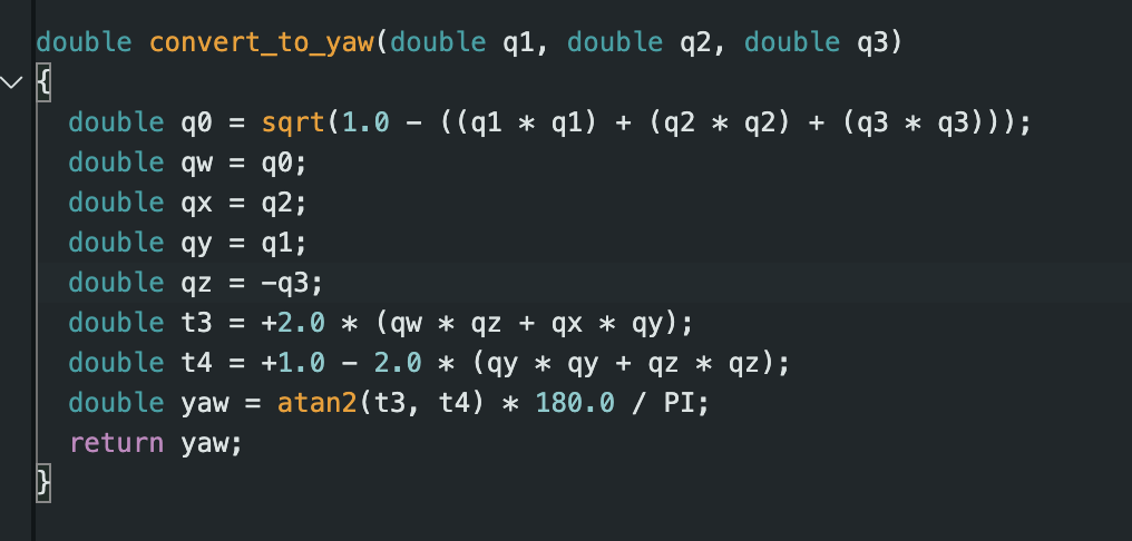
Followng the information from Wikipedia (and some help from ChatGPT), I implemented the conversion from quarterion
to angular yaw.
The ICM-20948 gyroscope has configurable full-scale ranges: ±250, ±500, ±1000, and ±2000 degrees per second. The
default is typically ±250 dps, which might be insufficient for very rapid rotations. The DMP typically uses the
±2000 dps setting. The 2000 dps range is more than adequate for robotic car applications, where typical rotations
rarely exceed a few hundred dps. The range can be set with ICM_20948_setGyroFullScale() if using raw gyro data.
With DMP, this is handled automatically when initialized it. Other limitations include magnetic interference or
high-frequency vibrations might introduce noise.
PI Controller
First, I focussed on P control and finding an appropriate Kp value. I kept Ki and Kd 0. Our motor driver has PWM
values in the range 0
to 255. I decided that my car should go a maximum of 2000 mm from the wall at max speed and then begin to slow
down. Taking scaling into consideration, I wanted a max PWM output of around 100-150. This corresponds to Kp
values ranging from 0.05 to 0.075.
i decided to test out a few Kp values, and saw that Kp of 0.05 semmed to work best. I also changed my ToF sensors
to work on long distance mode since they should be able to detect the wall from 6+ feet away.
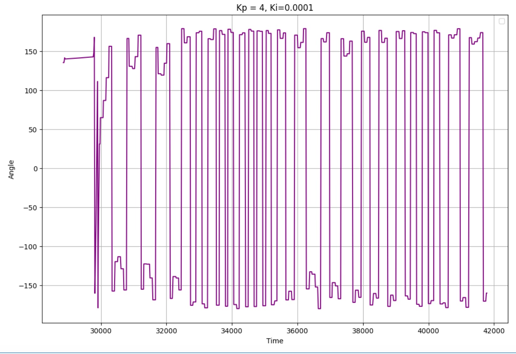
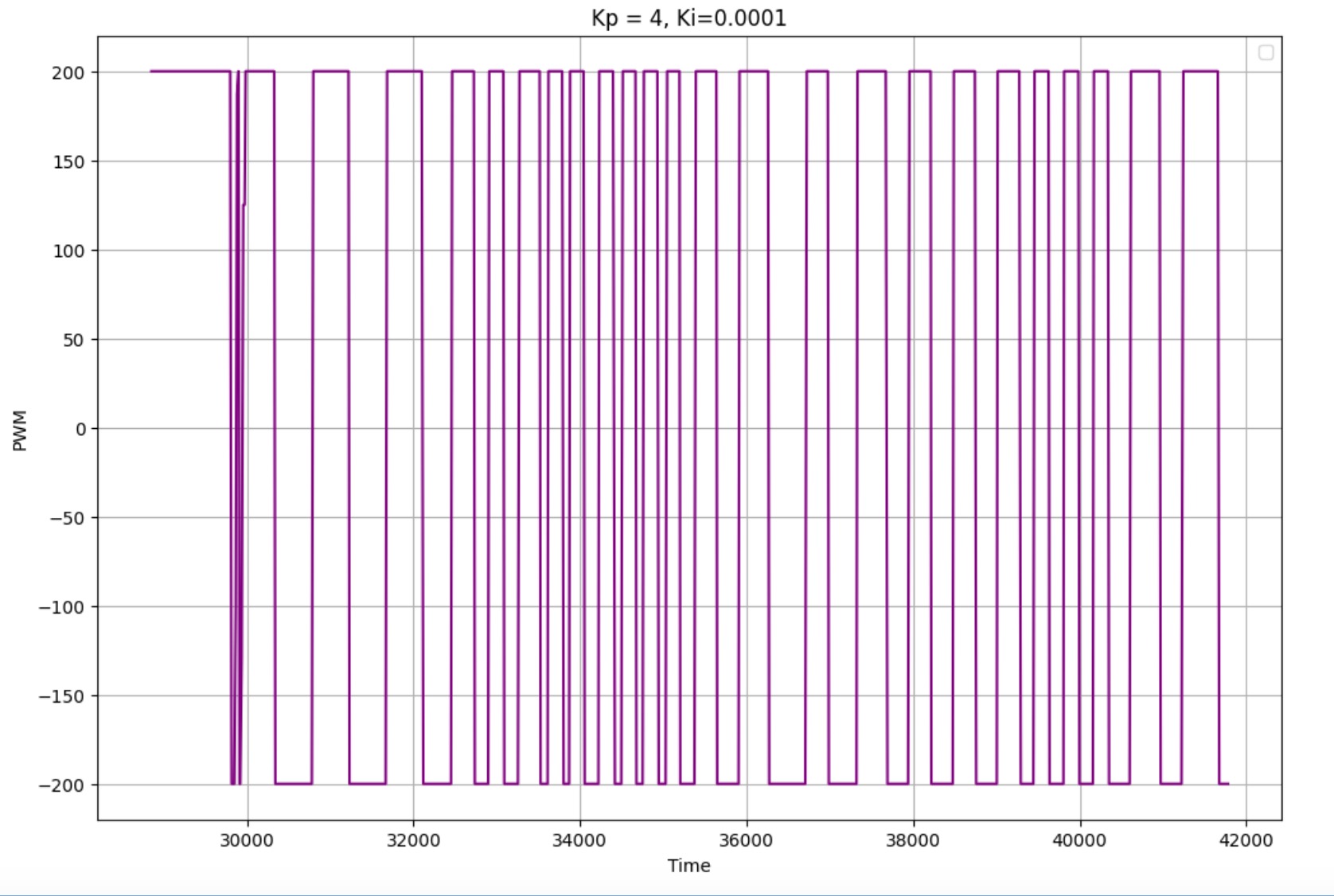
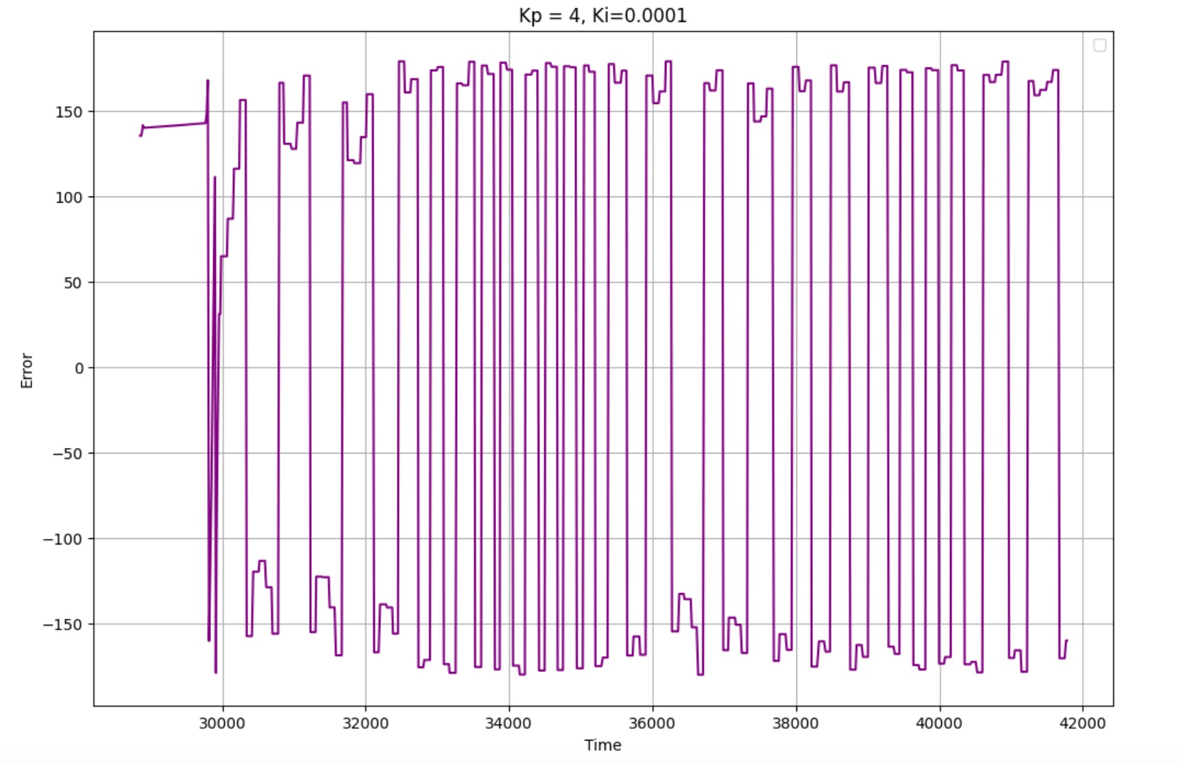
I tested various KP values starting at 0.05 (this was my KP value from lab 5). I was getting extremely low PWM
values with this KP so I tested larger KP values. I started testing at KP = 5 but found this was too big and the
car was oscillating a lot. I then reduced the KP value to 4.0 and saw pretty good correction results. Here are
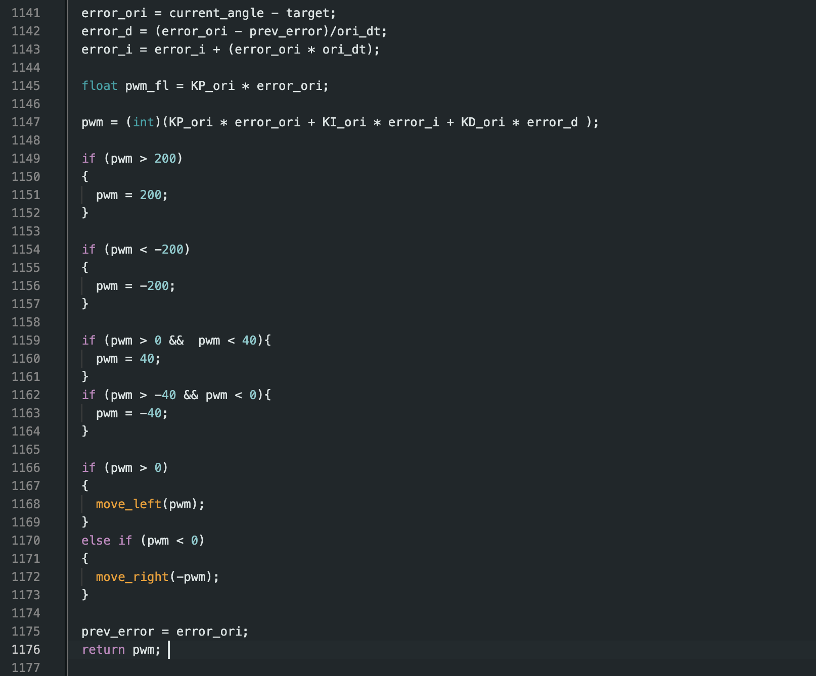
graphs of KP set to 4.0, with a target angle of 0. While correcting the robot did move forwards/backwards a bit
and I noticed that the PWM values oscillated between 200 and -200 which was what had been set as max speed.
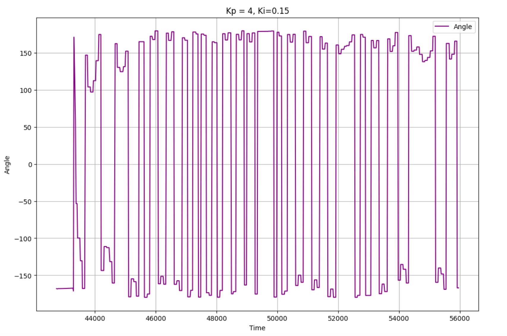
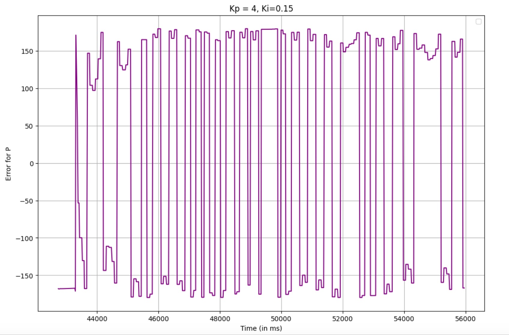
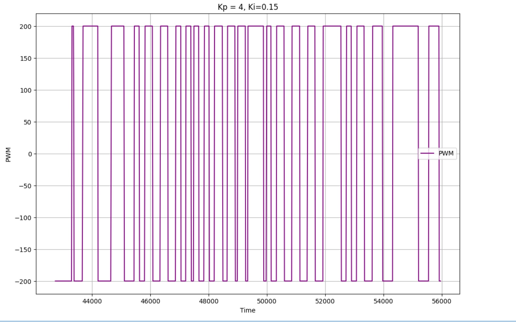
Next, I implemented the KI controller. I started off with KI value of 0.15 and saw pretty good performance. Any
larger/smaller KI values led to a lot of oscllations of the car. KI of 0.15 had similar performance to just the KP
controller. Here are graphs for KP = 4.0 and KI = 0.15.
Finally, here is a good video demonstrating the correction for target angle 0.
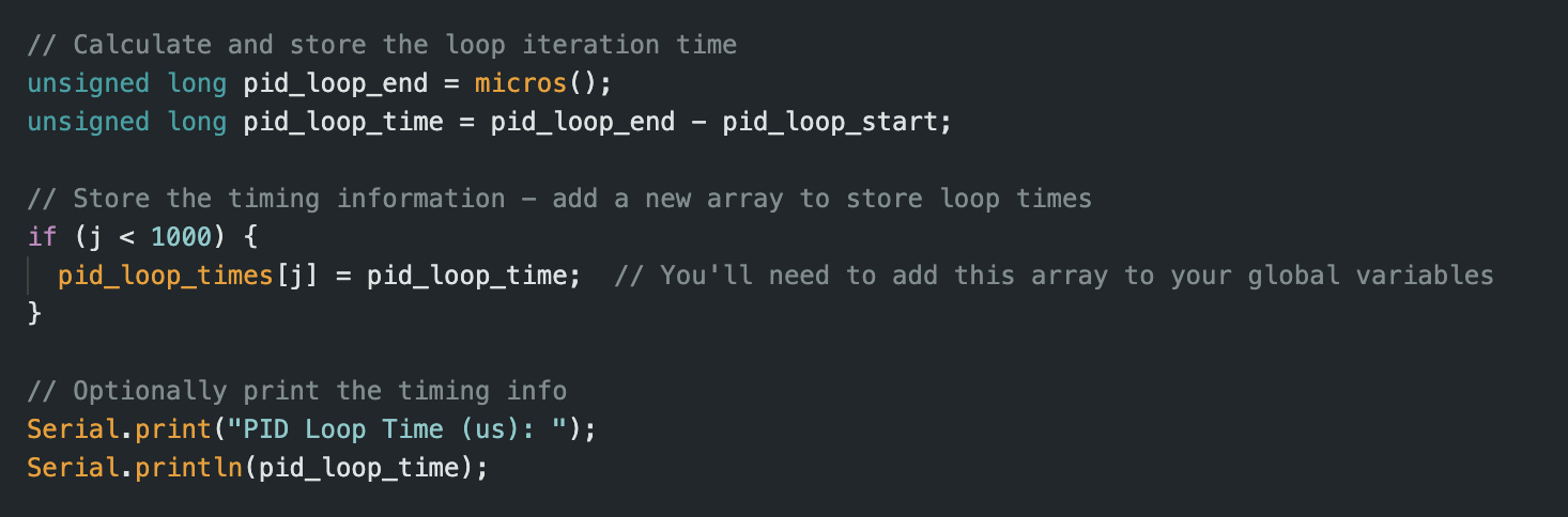
Sampling
I used similar code as Lab 5 to test frequency of the IMU collection and PID loops. For this lab I found that the
two loops had pretty similar frequencies unlike Lab 5. The ICM-20948's DMP is specifically designed for high-speed
motion processing. It operates at a high internal sample rate (up to 1.1 kHz) and processes the sensor fusion
algorithms in dedicated hardware. This offloads computation from the main processor and ensures consistent data
delivery.
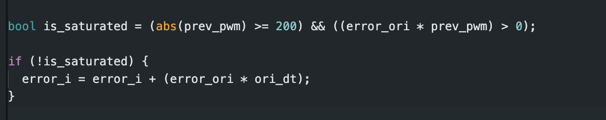
Additional 5000 Level Task: Wind-up
When implementing a PID controller, it's essential to address integrator wind-up, a common issue that occurs when
the system can't achieve the commanded output. This happens when your controller demands more than your motors can
physically deliver, causing the integral term to grow unnecessarily large.
In my orientation control implementation, I've included wind-up protection similar to what I used in distance
control. The key idea is to prevent the integral term from accumulating when it can't actually influence the
system:
Conclusion
This lab was very useful in understanding how I can use the IMU for orientation control. I managed to
implement orientation control using a PI controller with the IMU's Digital Motion Processor. The proportional
term provided immediate response to heading errors, while the integral term proved essential for overcoming motor
deadband and eliminating steady-state errors. Anti-windup protection prevented integral saturation, and the DMP's
sensor fusion eliminated gyroscope drift.
References
I referenced Nila Narayan and Mikayla Lahr's work for Lab 6. Further, Jennie Redrovan, Lulu Htutt and I worked on
this lab together and collaborated while figuring out the PI controller. While working on the lab we were
unfortunately left with only 1 working battery and therefore all 3 of us shared the hardware but ran the code
separately.