The purpose of this lab was to design a system so that our robots can navigate through the map following a set of
waypoints as quickly and accurately as possible.
Chosen design
The robot was required to navigate through the following waypoints in order:
(0,0) → (3,0) → (3,-3) → (5,-3) → (5,3) → (3,3) → (3,0) → (0,0)
I chose to use a waypoint to waypoint navigation system that used PID control for both orientation and angle. This
method assumes that the robot starts almost correctly at each waypoint and uses PID control to first angle the
robot
towards the next waypoint and then position control to go straight to it.
Alternate method
Initally, I tried to use localization along with my PID control so that the robot can accurately identify its
current position at each step. However, my localization was pretty inaccurate and I was not getting good readings,
particularly for the point (5, -3) and the waypoints around it like in Lab 11. Since my localization was not
significantly increasing the
accuracy I decided to switch to pure PID control and just assume that the robot begins perfectly positioned at
each
waypoint.
Code Set-Up
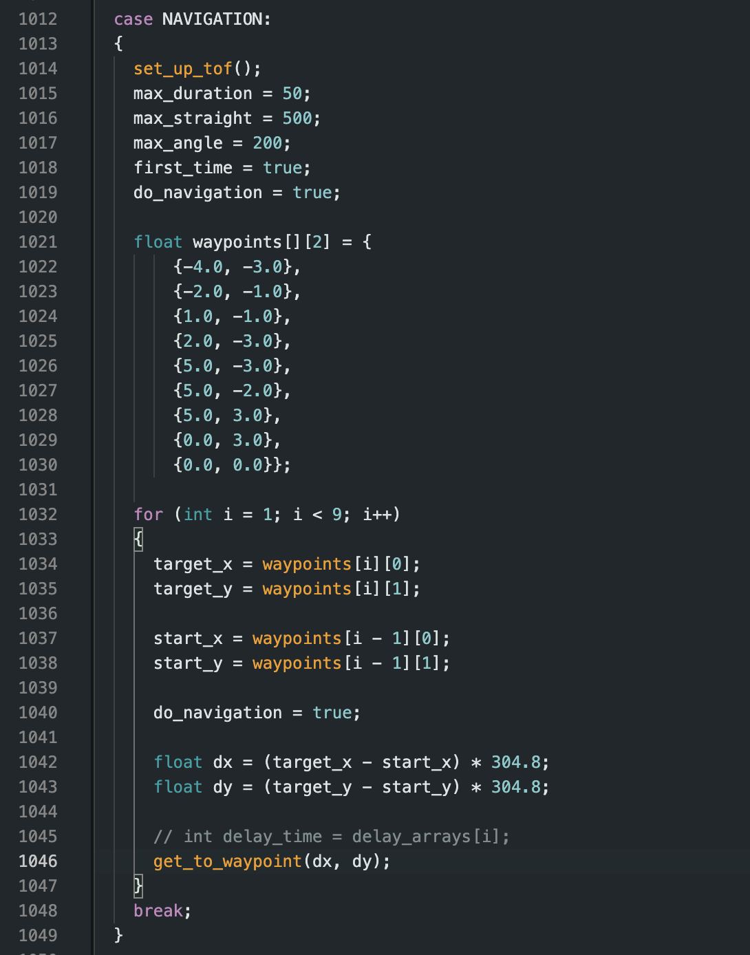
First, I implemented a function called get_to_waypoint(dx, dy). This function takes in the difference in the x and
y coordinates of the current waypoint the robot is at and the next waypoint it needs to get to. It then
"navigates" the robot from the current point to the next. This happens in three main steps. First, PID orientation
control is used so that the robot is angled in the direction of the next waypoint. Then, PID position control is
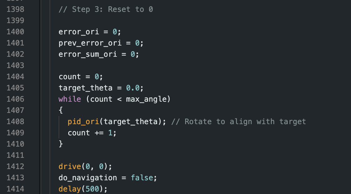
used to get the robot to the next waypoint. Finally, I again use PID orientation control to realign the robot to
0° so that the whole process can restart. Realigning the robot at the end of each "navigation" helped maintain the
accuracy of my PID orientation control. I then added another case called NAVIGATION which loops through each
waypoint and calls the function get_to_waypoint() at each step.
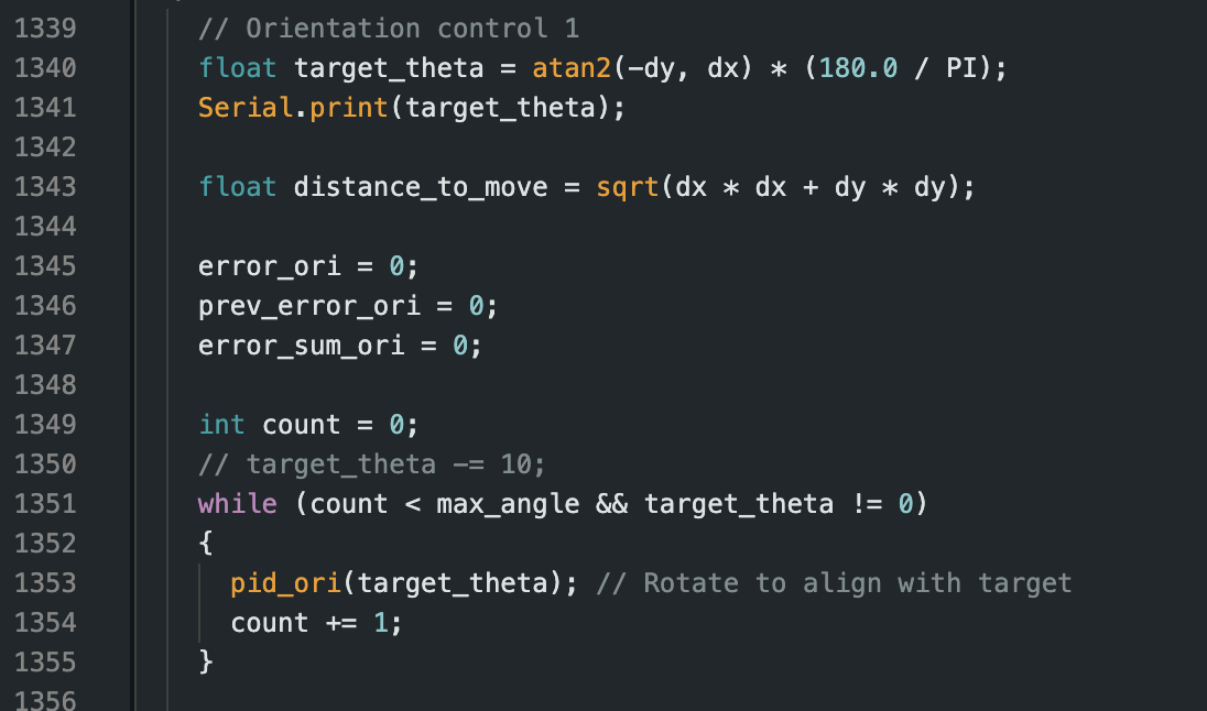
To calculate the required angle heading, I used the following equations. For the atan2 function, I
fixed the
coordinate by matching up the orientation of the IMU on the car with the given 0° for the world axes. Since my IMU
was mounted such that 0° pointed in the -y direction on the map, I used atan2(-dy, dx) to
align the robot's heading with the map's global coordinate frame.
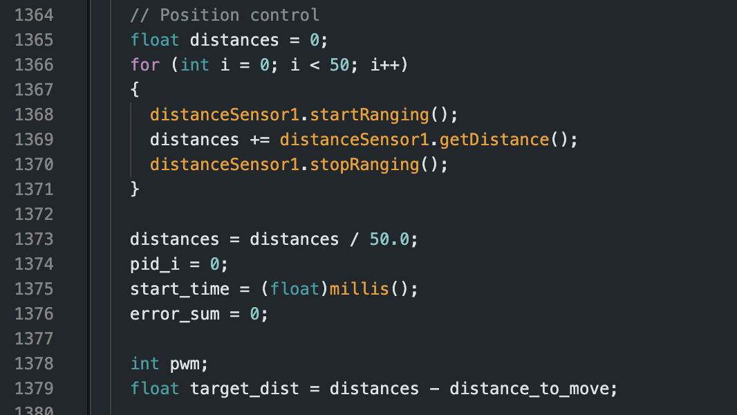
The equations above compute the direction and distance between the robot's current position and its target
waypoint. Below is the code that shows that 3 parts of this function:
I tuned the PID gains empirically. For orientation, I found that a higher proportional gain caused faster turning,
but
overshooting became an issue. I tuned the derivative term to dampen this overshoot. For linear PID control, I used
a
low integral gain to minimize steady-state error and prevent oscillations. For the loops I just estimated the time
it would take for my robot to get to the right linear/orientation
positions.
Results
Once I had all the code set-up I performed a few runs with my robot.
The robot successfully navigated to all waypoints within a 10–15 cm error range for most of the waypoints.
The best run is shown below where my robot
managed to get to all waypoints but for some reason went in the opposite direction at the last one. I was having
consistent issues with the last two waypoints, particularly with orientation PID for the last one. I think it was
probably a DMP issue/error accumulation and for the best run I got, my robot just goes in the opposite direcion
for this run.
Jennie, Lulu and I worked as a team for this lab and were together able to get the above code/run.
Conclusion
Overall, this lab was challenging but fun. It was pretty cool to be able to put a semester's worth of work
together and see our robots navigate through a map !
References
I referenced Mikayla's work for Lab 12. Lulu, Jennie and I also worked as a team on this lab. We also worked with
Aidan, Jorge and Henry to figure out the best approach.